Wednesday, May 25, 2016
Like many of my colleagues this past semester, I decided it would be fun to build a heavyweight battlebot ("The Dentist") for season 2 of the Battlebots TV show. "The Dentist" involved spinning up a 200KJ energy storage drum, and being as mechanically incompetent as I am, I decided that clearly my contribution to the sport would be some kind of absurd power system involving hundreds of volts and large motors.
I went and bought a few Prius inverters and dusted off the old Bremsthesis bits, and began this year's adventure into turning on someone else's hardware.
New boards, better boards
Wow, these motors have resolvers on them! So much more convenient than our contraption built out of 3D-printed mounts and analog hall sensors. Even more conveniently, there is a rather expensive IC that takes resolver input and outputs quadrature encoder pulses. Rather fortunately, this IC can be sampled from Analog Devices, or purchased from unofficial eBay vendors for about $15.
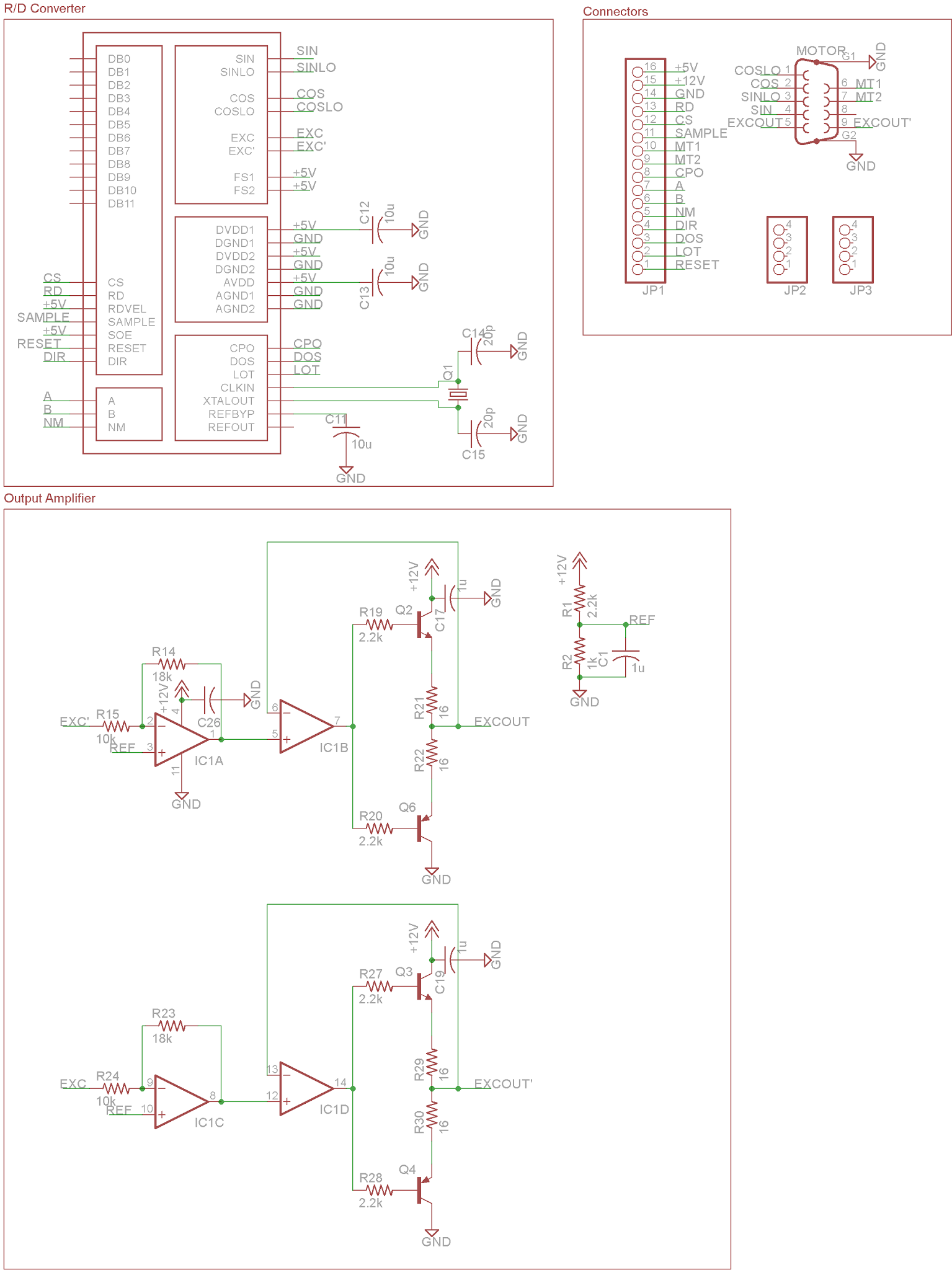
Implementing the IC using the datasheet notes is fairly straightforward; the only tricky part is getting the output amplifiers right (the sine/cosine generation on the chip itself is the output of a DAC, and is unsuitable for driving a resolver directly):
Layout is a little less straightforward. The following daughtercard works, but has about 1 LSB worth of noise:
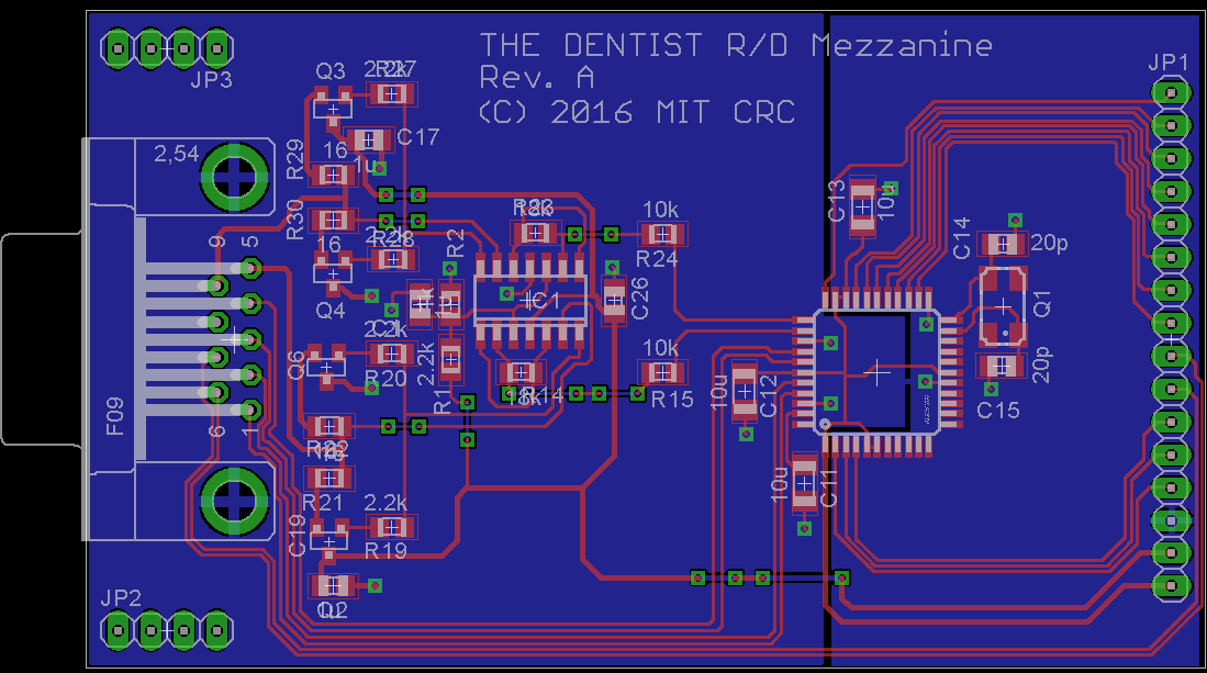
I could probably do better, but who needs 12 bits of position accuracy anyway?
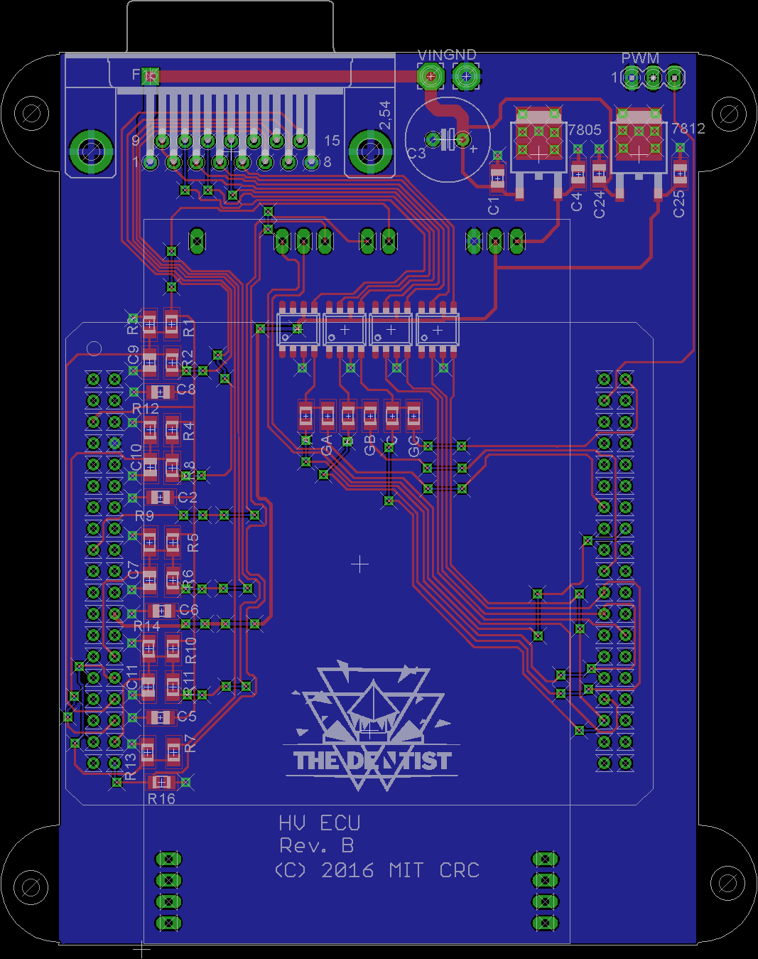
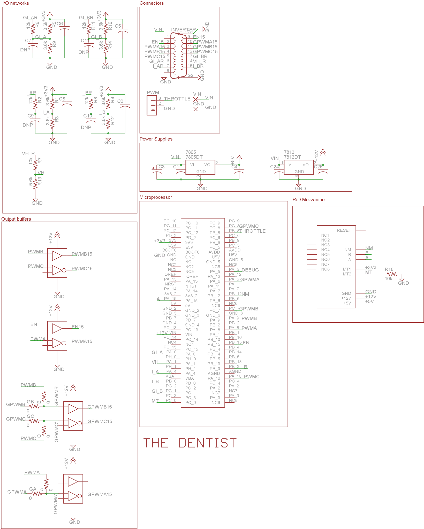
The actual interface board for the Prius module remains largely unchanged in design from last year, the only changes being it uses the Morpho headers and is all surface mount, because hell if I'm using sockets in a combat robot.
New this year! Prius inverter pinouts
| Pin # | Name | Description | Notes |
|---|---|---|---|
| 1 | IGCT | Gate drive power in | Reverse-protected, ~9-16V |
| 2 | GIVB | Small inverter, current sense V | Redundant with GIVA |
| 3 | GIVA | Small inverter, current sense V | 50mV/A, zero-centered, isolated |
| 4 | GIWB | Small inverter, current sense W | Redundant with GIWA |
| 5 | GIWA | Small inverter, current sense W | 50mV/A, zero-centered, isolated |
| 6 | GWU | Small inverter, phase input W | Inverting, 12V logic, isolated; no float |
| 7 | GVU | Small inverter, phase input V | See above |
| 8 | GUU | Small inverter, phase input U | See above |
| 9 | GIVT | Small inverter temperature | Unknown behavior, probably ratiometric |
| 10 | GFIV | Small inverter fault indicator | Probably open-collector |
| 11 | GSDN | Small inverter ENABLE | 12V logic, setting low floats all phases |
| 12 | MIVT | Large inverter temperature | Unknown behavior, probably ratiometric |
| 13 | MFIV | Large inverter fault indicator | Probably open-collector |
| 14 | MSDN | Large inverter ENABLE | 12V logic, setting low floats all phases |
| 15 | GINV | Gate drive power GND | Isolated |
| 16 | MIWA | Large inverter, current sense W | 25mV/A, zero-centered, isolated |
| 17 | MIWB | Large inverter, current sense W | Redundant with MIWA |
| 18 | MIVA | Large inverter, current sense V | 25mV/A, zero-centered, isolated |
| 19 | MIVB | Large inverter, current sense V | Redundant with MIVA |
| 20 | NC | No connection | |
| 21 | NC | No connection | |
| 22 | NC | No connection | |
| 23 | MWU | Large inverter, phase input U | Inverting, 12V logic, isolated; no float |
| 24 | MWV | Large inverter, phase input V | See above |
| 25 | MWW | Large inverter, phase input W | See above |
| 26 | VH | Bus voltage | Ratio not yet determined |
| 27 | OVH | Inverter overvoltage | Probably open-collector |
| 28 | GND | Chassis ground | Leave unconnected |
Power stage notes: Sides are probably CM400 and CM200-class IGBT's. Stock switching freqency is 5KHz; performance becomes rather poor past about 15KHz as internal delays and deadtime introduce severe distortion in synthesized waveforms. Current sensors saturate at 400 and 200A; the power module has fast overcurrent detection set somewhere around there (the entire inverter will automatically float if the phase currents are too high). Diodes are quite small in comparison to the IGBT's, and are probably not rated to full inverter current.
Sleeker firmware
Thanks to mostly me, the original Brems-code had bloated to rather ungainly proportions, featuring contexts, event loops, buffers, debuggers, and more classes than should ever be in a two-person microcontroller project. It was time to downsize; conveniently enough, Ben was working on an encoder-based FOC controller for his robot leg project, so I decided to borrow bits of his code and mix it with my own. The new code is here.
Tidbits of particular note:
a = new FastPWM(PWMA);
b = new FastPWM(PWMB);
c = new FastPWM(PWMC);
NVIC_EnableIRQ(TIM1_UP_TIM10_IRQn); //Enable TIM1 IRQ

TIM1->DIER |= TIM_DIER_UIE; //enable update interrupt
TIM1->CR1 = 0x40; //CMS = 10, interrupt only when counting up
TIM1->CR1 |= TIM_CR1_ARPE; //autoreload on,
TIM1->RCR |= 0x01; //update event once per up/down count of tim1
TIM1->EGR |= TIM_EGR_UG;

TIM1->PSC = 0x00; //no prescaler, timer counts up in sync with the peripheral clock
TIM1->ARR = 0x4650; //5 Khz
TIM1->CCER |= ~(TIM_CCER_CC1NP); //Interupt when low side is on.
TIM1->CR1 |= TIM_CR1_CEN;
This snippet of code sets up Timer 1 to run at 5Khz in center-aligned mode; that is, the center points of the switching waveforms when all three channels are off are aligned. This allows us to sample current when none of the phases are switching, hopefully reducing sensor noise. TIM1->ARR controls the switching frequency; halving its value doubles the switching frequency.
RCC->APB2ENR |= RCC_APB2ENR_ADC1EN; // clock for ADC1
RCC->APB2ENR |= RCC_APB2ENR_ADC2EN; // clock for ADC2

ADC->CCR = 0x00000006; //Regular simultaneous mode, 3 channels

ADC1->CR2 |= ADC_CR2_ADON; //ADC1 on
ADC1->SQR3 = 0x0000004; //PA_4 as ADC1, sequence 0

ADC2->CR2 |= ADC_CR2_ADON; //ADC2 ON
ADC2->SQR3 = 0x00000008; //PB_0 as ADC2, sequence 1

GPIOA->MODER |= (1 << 8);
GPIOA->MODER |= (1 << 9);
GPIOA->MODER |= (1 << 2);
GPIOA->MODER |= (1 << 3);
GPIOA->MODER |= (1 << 0);
GPIOA->MODER |= (1 << 1);
GPIOB->MODER |= (1 << 0);
GPIOB->MODER |= (1 << 1);
GPIOC->MODER |= (1 << 2);
GPIOC->MODER |= (1 << 3);
This bit configures the ADC's. We are cheating a little here; the ADC's are set up in sequence mode, but the sequences are length 1. Because only two values are necessary for basic operation we don't have to worry about dealing with the sequencing (somewhat useful, as mbed somehow goes and clobbers ADC_EOC flag functionality).
void zero_current()
{
    for (int i = 0; i < 1000; i++) {
        ia_supp_offset += (float) (ADC1->DR);
        ib_supp_offset += (float) (ADC2->DR);
        ADC1->CR2  |= 0x40000000;
        wait_us(100);
    }
    ia_supp_offset /= 1000.0f;
    ib_supp_offset /= 1000.0f;
    ia_supp_offset = ia_supp_offset / 4096.0f * AVDD - I_OFFSET;
    ib_supp_offset = ib_supp_offset / 4096.0f * AVDD - I_OFFSET;
}
This function tries to compute an additional offset (caused by sensor drift, etc.) every time the controller resets; this is in addition to any measured calibration errors caused by resistor inaccuracies or AVDD error.
p = pos.GetElecPosition() - POS_OFFSET;
if (p < 0) p += 2 * PI;

float sin_p = sinf(p);
float cos_p = cosf(p);

ia = ((float) adval1 / 4096.0f * AVDD - I_OFFSET - ia_supp_offset) / I_SCALE;
ib = ((float) adval2 / 4096.0f * AVDD - I_OFFSET - ib_supp_offset) / I_SCALE;
ic = -ia - ib;

float u = CURRENT_U;
float v = CURRENT_V;

alpha = u;
beta = 1 / sqrtf(3.0f) * u + 2 / sqrtf(3.0f) * v;

d = alpha * cos_p - beta * sin_p;
q = -alpha * sin_p - beta * cos_p;

float d_err = d_ref - d;
float q_err = q_ref - q;

d_integral += d_err * KI;
q_integral += q_err * KI;

if (q_integral > INTEGRAL_MAX) q_integral = INTEGRAL_MAX;
if (d_integral > INTEGRAL_MAX) d_integral = INTEGRAL_MAX;
if (q_integral < -INTEGRAL_MAX) q_integral = -INTEGRAL_MAX;
if (d_integral < -INTEGRAL_MAX) d_integral = -INTEGRAL_MAX;
vd = KP * d_err + d_integral;
vq = KP * q_err + q_integral;
if (vd < -1.0f) vd = -1.0f;
if (vd > 1.0f) vd = 1.0f;
if (vq < -1.0f) vq = -1.0f;
if (vq > 1.0f) vq = 1.0f;
The rest of the code should be fairly self-explanatory; the mbed project should run out of the box on a Nucleo-F446RE.