Thursday, December 22, 2011
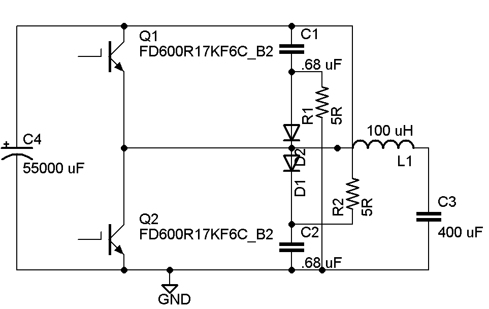
The big new hit in the coiling community is the "QCW" topology - essentially a DRSSTC with an arbitrary waveform generator on the bus. QCW's run at long pulse lengths (typically 10 ms) and relatively low peak currents (only a few hundred amps, compared to the 1000+ amps in large DRSSTC's). By ramping up the bus voltage slowly, QCW's can maintain low topload voltages while producing long spark lengths, thereby avoiding the flashover problems associated with smaller coils. For reference, Steve Ward's coil did ~60" of spark off a 9" secondary. The current theory is that the gradually increasing output voltage allows the spark to follow its own ion channel better, leading to longer sparks. The core of the QCW DRSSTC, and the part that sets it apart from classic DRSSTC's, is that your usual fixed bus voltage (doubler/variac/boost converter/whatever) is replaced by a regulated step-down converter. The converter modulates the pulsed output from a capacitor bank on its DC bus into a ramp, which then powers the bridge in the DRSSTC. Rough schematic of the power end:
Nothing special - just a synchronous buck/class-D amplifier. Q1 and Q2, which are IGBT modules, chop up the DC input, and L1 and C3 form a low-pass filter which turns the square wave back into a DC voltage. Q2 is essential because it allows the output capacitor to be discharged rapidly. C1, C2, R1, R2, D1, D2 form RCD snubbers on the bricks to keep them nice and cool. Bricks need beefy gate drives, especially important here since we are hard switching:
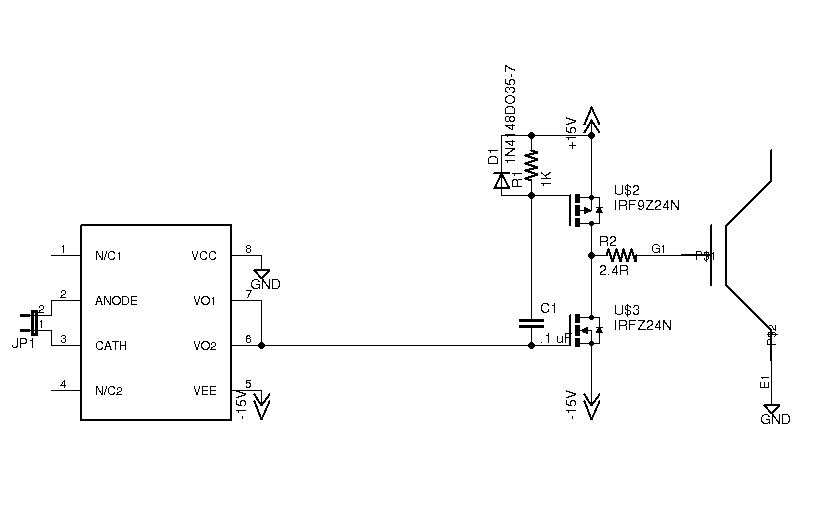 The optocoupler is a 2.5A gate drive which drives the P-N half-bridge, which drives the gate. The P-N bridge is necessary to charge the 200nF+ gate capacitance of the brick as quickly as possible.
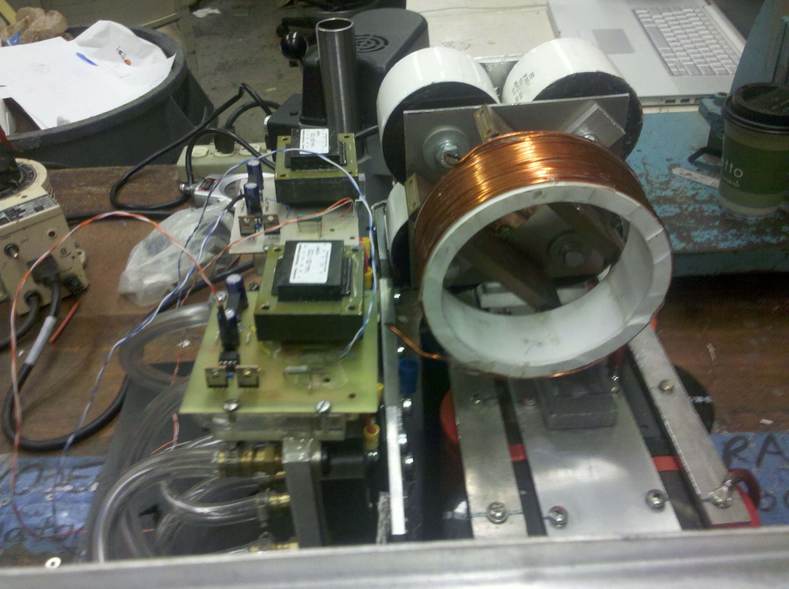
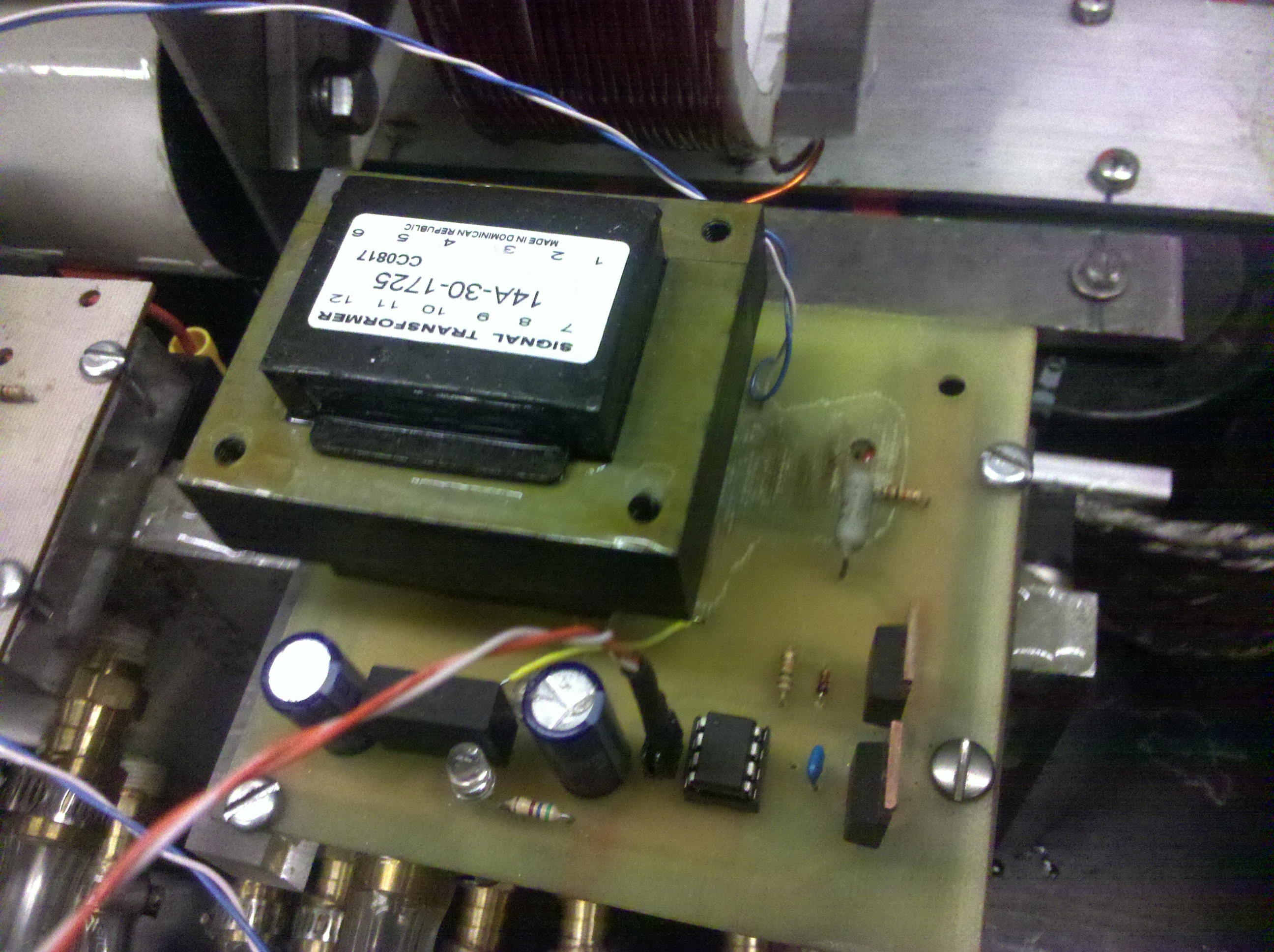
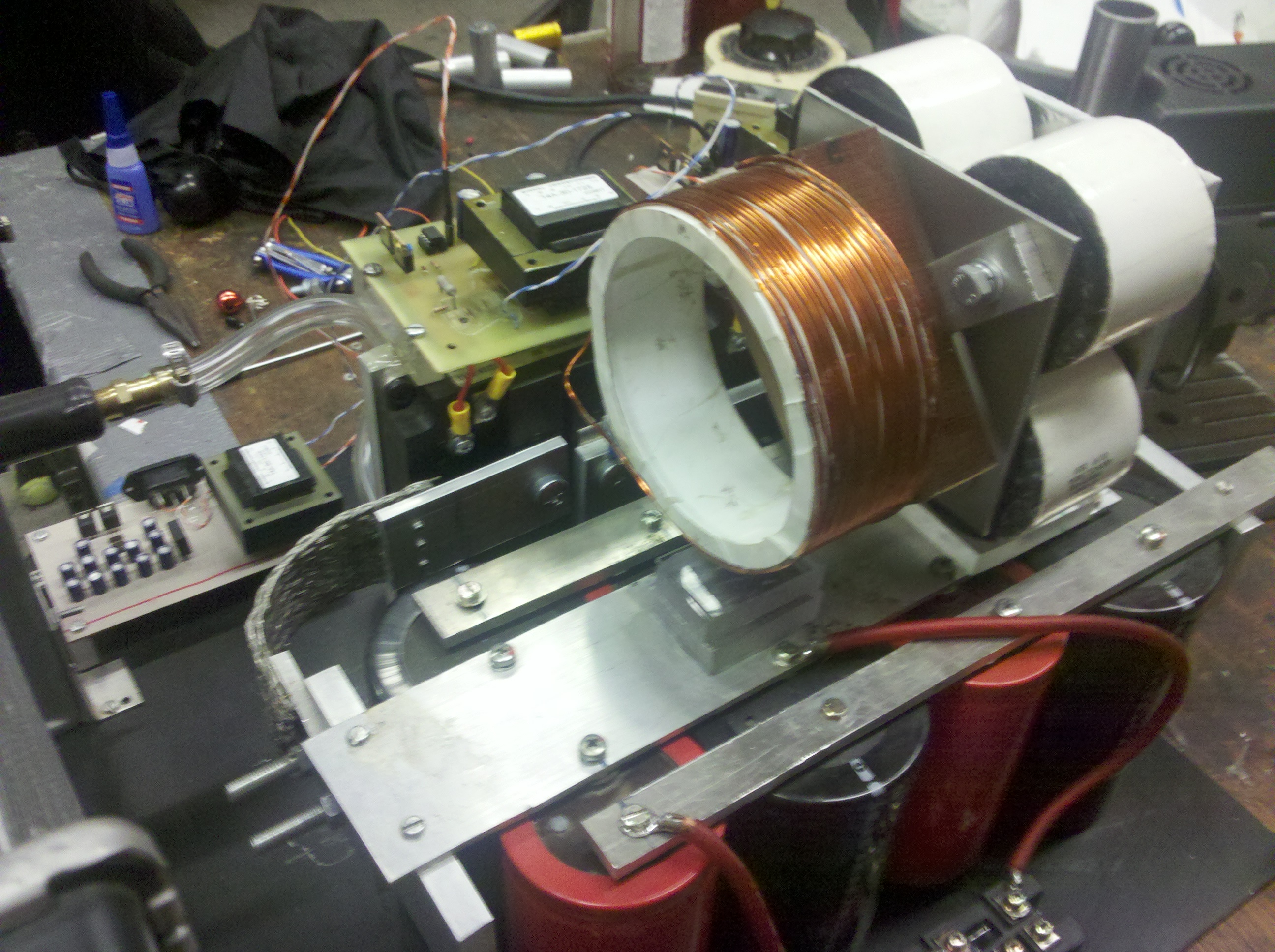
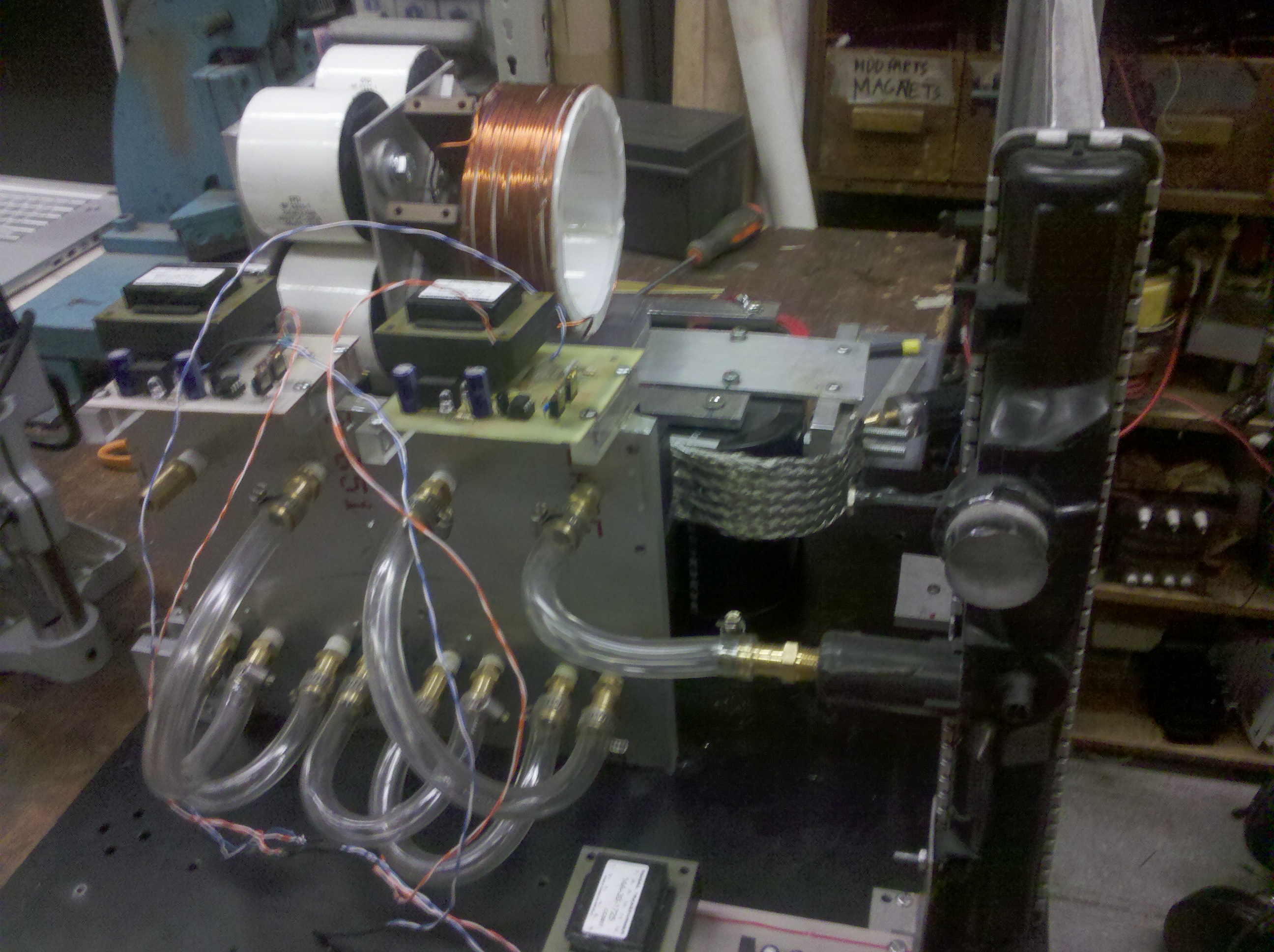
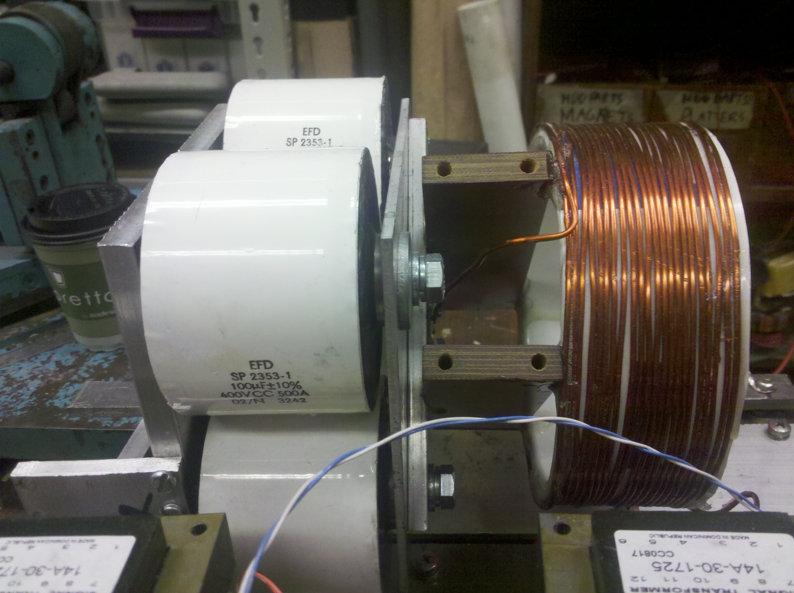
The controller is just a microcontroller (currently an Mbed, but soon to be an STM32F4). The built-in ADC is used to compare the output voltage to two thresholds, a lower bound and an upper bound. If the output is lower than the lower bound, the micro turns on the high side, and if its higher than the upper bound, it turns on the low side (hysteresis control/delta modulation/bang-bang control/cycle-by-cycle limiting). It remains to be seen whether the naive software-only implementation can track the Tesla coil load quickly enough regulate properly... And finally, pictures of all this in real life:
EDIT 3/23/2012: damn I fail at designing RCD snubbers. Schematic updated.