Wednesday, February 11, 2015
Previously we (really just Nick) had managed to mount up the rotor and stator from a Ford hybrid and turn it into a working motor. The next step was to find a suitable controller for the motor, and what better place to look than the guts of a Toyota Prius?
There has been some previous work done on the Prius inverter; this fellow here has a fairly extensive teardown of the assembly, complete with glamour shots of the gooey innards of the brick. I'll supplement his information with the following:
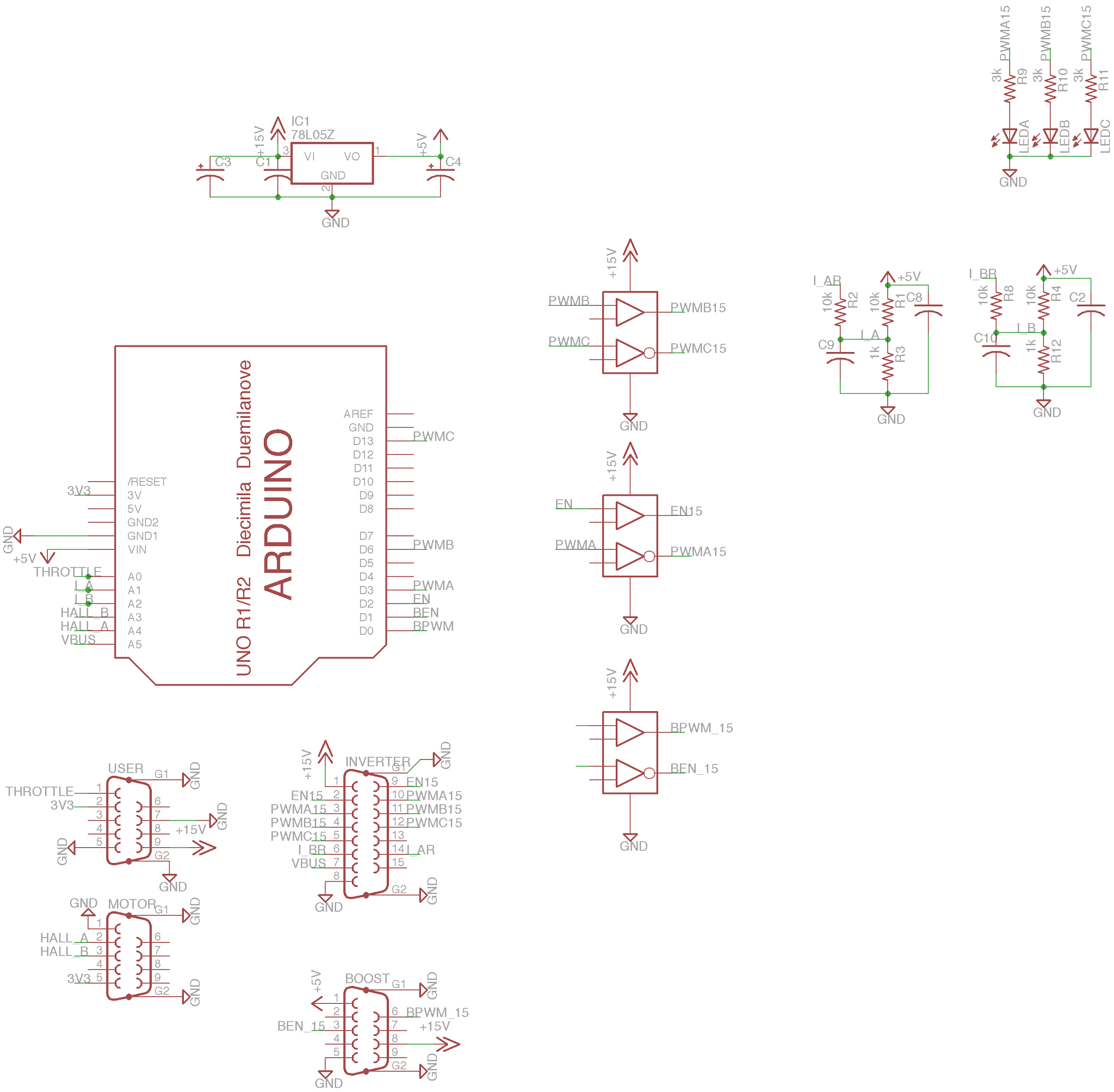
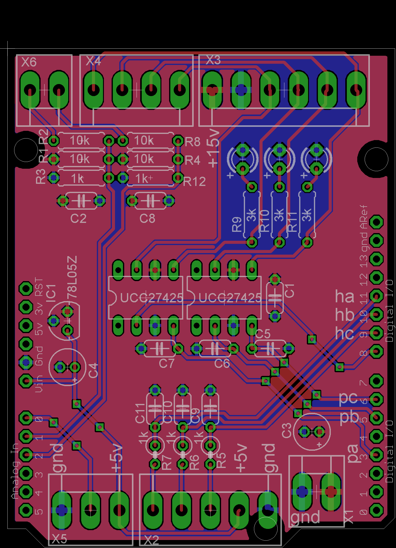
The first step was to build a board to interface with the module. A bit of Eagle layout work gave the following board and schematic:
The board is Arduino-shaped, but is actually meant to mount atop one of these:
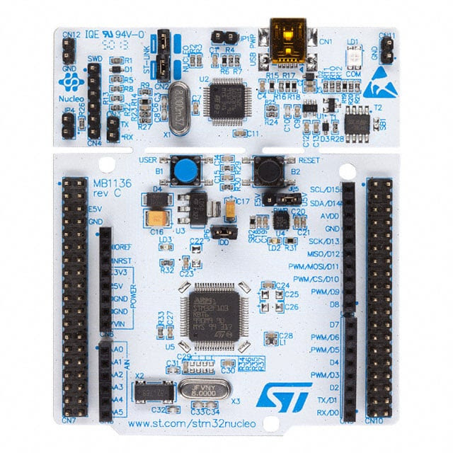
An STM32F4 Nucleo, part of ST's latest attempt to push their high-performance ARM microcontrollers and actually a pretty good one at that. The hardware pins are Arduino-compatible, and the board can be programmed via the Mbed online IDE. Sure, their libraries are as slow as balls, but even with the overhead of the Mbed libraries the Nucleo still has about 10x the performance of an Arduino, not to mention all-important hardware floating-point support.
The board should be self-evident - X5 is a throttle input, X2 is hall sensors, X1 is 12V power, X3 and X4 control the two halves of the Prius brick (remember, there are two controllers in the brick!) in parallel, and X6 is a quick-and-dirty resistor-divider based input for the current sensors.
We have a board - firmware was next. You can download the firmware package here. A quick code walkthrough follows.
Motor commutation is interrupt-based, with throttle polling and (in the future) the current loop runnin in the main loop. Math is done in floating point thanks to the STM32F4's hardware FPU.
The
The routine is called at regular intervals (in the default firmware, 5KHz). It does two things: measure the time elapsed since the last commutation () and update the duty cycle via a table lookup.
In its current state the firmware isn't really production-ready; the lack of current control makes it too unwieldy for use on large vehicle, but it should at least get us off the ground for further testing.